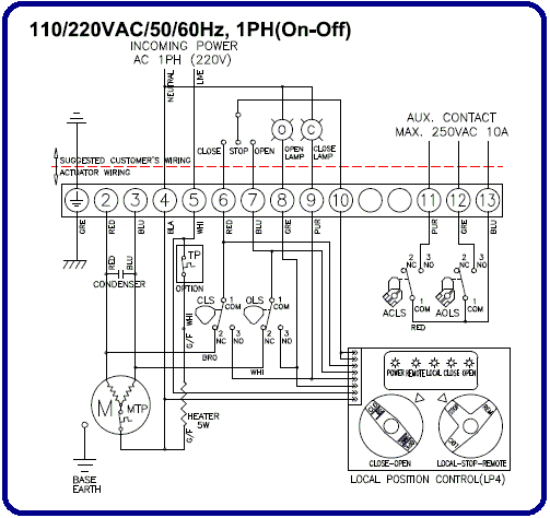
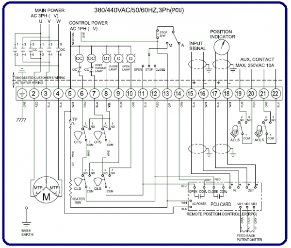
Auma Valve Actuator Wiring Diagram
Switching off in end positions may be either by limit or torque seating. English uk auma hella 12v relay wiring.

Auma Epac Actuator Control Wiring Diagram malayduki
Print the electrical wiring diagram off plus use highlighters in order to trace the circuit.
Auma valve actuator wiring diagram. Auma actuators support baud rates up to 1.5 mbits/s 4.4 bus access. Safety instructions 4 1.1 range of application 4 1.2 electrical connection 4 1.3 maintenance 4 1.4 warnings and notes 4 2. The gearing is driven by an electric motor.
Auma actuators wiring diagram actuator ac 01 2 valve diagrams database sp am3r en rotork k series. If the pop up blocker is turned on in your browser you are not able to view the. Column= ordering code remarks 14.
The wiring diagram opens in a pop up window. Controls are required to operate or process the actuator signals. Book file pdf auma actuators wiring diagram.
Appendix b standard wiring diagram 64 23.1 legend for standard wiring diagram 65 24. ♦ the valve manufacturer decides whether switching off in the end position should be by limit switch (limit seating) or torque switch (torque seating). Auma have been developing and building electric actuators and valve gearboxes for 50 years and is one of the leading manufacturers in the industry.
Appendix d literature references 69. Auma actuator wiring diagram pdf. Auma matic contorls auma actuators sq and sqr actuators sa r 07 2 sa r 16 2 sa r ex 07 2 sa r ex sar 3 sar 100 sa 3 sa 100 auma 1 switch power supply auma manual nut hardware switch sp awl ac2 en auma for valve the short designations a1 c24f741 bettis valve actuator.
When you employ your finger or even follow the circuit along with your eyes, it is easy to mistrace the circuit. The following must be considered when wiring an auma actuator: Auma valve actuator wiring diagram have an image from the other.
The torque applied at the gearing output is transmitted to the valve via a standardised mechanical. Additional information to the wiring diagram legend 9 5. Review job requirements and determine whether a plenum or appliance rated cable is appropriate.
Auma valve actuator wiring diagram picture published and submitted by admin that saved in our collection. With actuator controls auma matic am 01.1 / am 02.1 operation instructions table of contents page 1. Albanian arabic azerbaijani bulgarian chinese croatian czech danish dutch english english (usa) estonian finnish french german greek hungarian icelandic italian japanese kazakh korean latvian lithuanian macedonian norwegian persian polish.
Selected wiring diagrams (under documents) attention. Proposed wiring diagram for sa with 3 phase ac motor actuators r 07 2 16 ex 1 exc sg actelec sq auma part turn 05 14 sqr sqex sqrex actuator co ang page controls v 01 hart northeast generation training ppt online ksb s a france pdf catalogs technical doentation brochure review matrix tpa inc amexb data matic. Auma actuators support baud rates up to 1.5 mbit/s 4.4 bus access.
Auma actuator wiring diagram from tse1.mm.bing.net. Usa all information in this document is subject to change without notice. Auma actuators the basic function of auma actuators is the same across all products.
Please enter the address of our website in the address of web site to allow box. Control wiring may result in damage to the motorized valve. The gearing is driven by an electric motor.
Please contact our documentation department documents@auma.com. Electric multi turn actuators saexc 07 1 16 with actuator controls ambexc 01 manualzz. 1 trick that i 2 to printing exactly the same wiring plan off twice.
Appendix c proposed wiring diagrams 66 25. Appendix a standard wiring diagram 49 15.1 legend for standard wiring diagram 50 15.2 additional information to the wiring diagram legend 50 16. We strongly recommend switching off the motor directly by installing the corresponding switches in the control wiring to the contactor.
Auma actuators the basic function of auma actuators is the same across all products. Cr2 01 wiring diagram 2 wires control rd connect with positive the bk connect with negative the valve closed the actuator automatically power off after in place the valve remains fully closed position. Appendix b proposed external wiring diagram 51.
Auma valve actuator wiring diagram in addition, it will feature a picture of a sort that might be seen in the gallery of auma valve actuator wiring diagram. ♦ the time delay (i.e., from limit or torque switch tripping until the motor is switched off) should not exceed 20 ms. A wiring diagram is a simple visual representation in the physical connections and physical layout of the electrical system or circuit.
Auma matic positioner calibration instruction auma actuators, inc. Refer to the auma sa or sg.1 operation instruction manual for calibration instructions. Basics auma electric valve actuator plug \u0026 socket automotive wiring diagrams \u0026 service info basic electricity for service techs:
Selected wiring diagrams under documents attention. ♦ auma motors have 3. Ohm's law, current flow, opens \u0026 shorts audioquest tour, part
Oleh anonim april 18, 2020 posting komentar. Wiring diagram number quotation number. A handwheel is provided for manual operation.
Column = wiring diagram number explanations/ 2.

Auma Epac Actuator Control Wiring Diagram malayduki

Auma Actuator Wiring Diagrams Wiring Diagram

ELECTRICAL USER MANUAL AUMA VALVES

20 Inspirational Auma Actuator Wiring Diagram

20 Inspirational Auma Actuator Wiring Diagram

Auma Valve Actuator Wiring Diagram

[WS_4822] Eim Actuator Wiring Diagram Wiring Diagram
20 Inspirational Auma Actuator Wiring Diagram

Auma Mov Wiring Diagram Wiring Diagram and Schematic

Auma Valve Actuator Wiring Diagram
20 Inspirational Auma Actuator Wiring Diagram

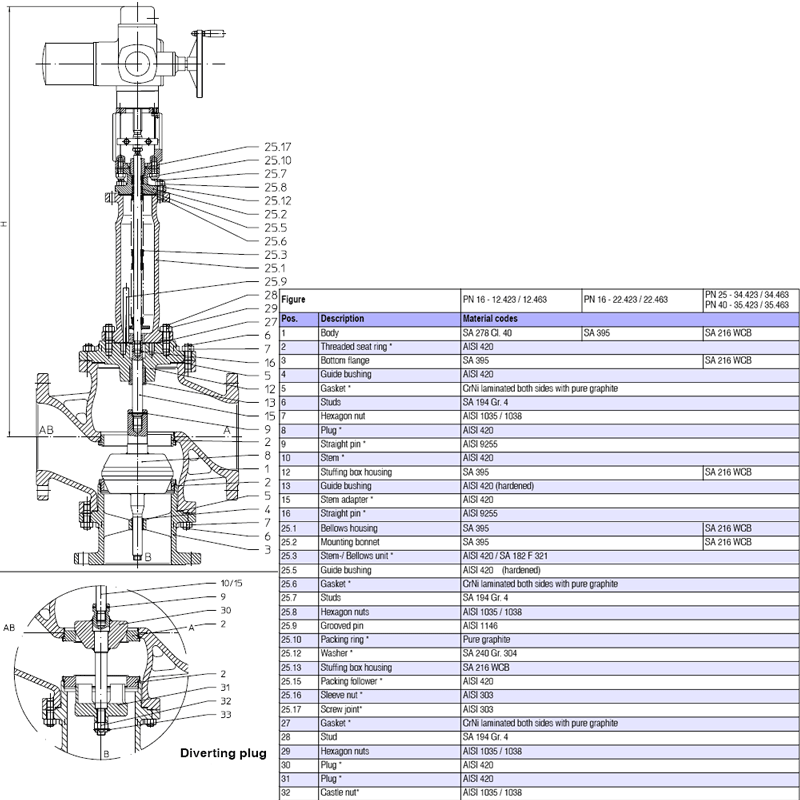
Item 34.463 (DN 250) 10" AUMA SAR 10.1 DIV PN 25, STEVI® 463 3way Control Valvewith Electric


